Basic principles of refrigeration
Heat : A Form of energy : Thermodynamics is the field of science that studies and deals with the mechanical action of heat.
Cold : Absence of Heat : Lower intensities of heat have atoms oscillating slower, the material considered cold or cool
How heat flows :The second law of thermodynamics states that heat always moves from the warmer body to the colder object.
How heat Measured : It can be measured only by measuring the effect it has on a material, such as a change in temperature, state, size, color, etc. This measurement is sometimes referred to as work, heat content or quantity of heat.
Measurement of heat is done in calories. One calorie is the amount of energy required to raise one gram of water one degree Celsius.
Temperature :Temperature is a property of matter that indicates the concentration or intensity of heat in a material.
Temperature Scale :
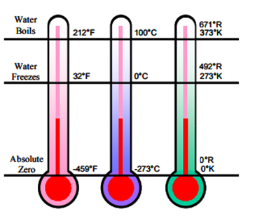
Temperature scales are based on effects of heat on water with references to boiling and freezing points of water.
The Fahrenheit temperature scale has water boiling at 212° and freezing at 32° with absolute zero at –459°.
The Celsius temperature scale has water boiling at 100° and freezing at 0° with absolute zero at –273°.
Scientists and engineers use the Kelvin and Rankin scales with 0° reference point at absolute zero. Kelvin scales uses Celsius increments, and Rankin uses Fahrenheit increments.
How Heat Flows
There are three ways heat flows, passes, moves or transfers between bodies
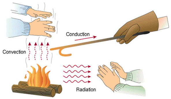
Conduction: the transmission of heat from one molecule to another within a material or from one material to another when they are held in direct contact.
Convection: the transfer of heat by another agent, such as air or water. heat passes by direct contact between the bodies, from molecule to molecule
Radiation: heat moves on waves of energy carried by photons of light in the infrared and visible portions of the electromagnetic spectrum and does not rely on molecules.
Heat Energy
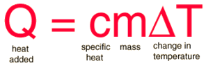
Specific Heat
The specific heat is the amount of heat per unit mass required to raise the temperature by one degree Celsius.
There are two types of heat categorized by the effect heat has on a material
Sensible Heat :Indicates heat absorbed or rejected by a material that accompanies or causes a change in temperature. This change can be detected by the sense of touch and measured with a thermometer.
Latent Heat : indicates heat absorbed or rejected by a material that accompanies or causes a change of physical state and seems to disappear or hide into the material without having an effect on its temperature. This is also known has ‘hidden’ heat
Enthalpy is the sum of sensible heat and latent heat. The unit is kJ/kg, or kcal/kg.
Refrigeration
Refrigeration is the process of removing heat from an enclosed space or from a substance for the purpose of lowering the temperature.
Types of Refrigeration System
- Vapor Compression Refrigeration System
- Vapor Absorption Refrigeration System
- Vapor Ejection Refrigeration System
- Air Cycle Refrigeration
- Vortex Tube Refrigeration
- Thermo-electric Refrigeration
- Thermo-acoustics Refrigeration
- Magnetic Refrigeration
- Cascade System
- Cryogenics
Sensible and latent heats of water at different phases
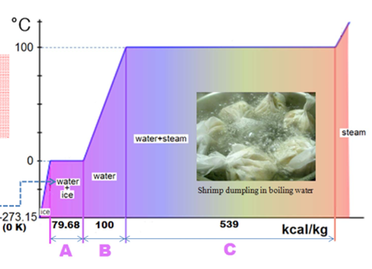
B = Sensible heat of water
C = Latent heat of vaporization of water at 100 °C
Vapor Compression Refrigeration System
Vapor Compression Refrigeration System Major Components: (i) Compressor, (ii) Condenser Coil, (iii) Expansion Valve and (iv) Evaporator Coil. Chemical Refrigerants such as R-12, R-22 or R-134a are used to provide refrigeration effect.
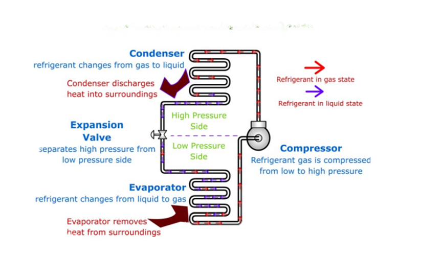
Refrigeration cycle
The Vapor-Compression Refrigeration Cycle is comprised of four steps
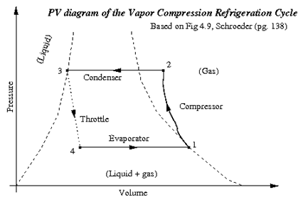
Part 4: Evaporation : The low pressure, low temperature refrigerant enters the evaporator, which is in contact with the cold reservoir. Because a low pressure is maintained, the refrigerant is able to boil at a low temperature. So, the liquid absorbs heat from the cold reservoir and evaporates. The refrigerant leaves the evaporator as a low temperature, low pressure gas and is taken into the compressor again, back at the beginning of the cycle
Part 1: Compression : In this stage, the refrigerant enters the compressor as a gas under low pressure and having a low temperature. Then, the refrigerant is compressed, so the fluid leaves the compressor under high pressure and with a high temperature.
Part 2: Condensation : The high pressure, high temperature gas releases heat energy and condenses inside the “condenser” portion of the system. The condenser is in contact with the hot reservoir of the refrigeration system. (The gas releases heat into the hot reservoir because of the external work added to the gas.) The refrigerant leaves as a high pressure liquid.
Part 3: Throttling : The liquid refrigerant is pushed through a throttling valve, which causes it to expand. As a result, the refrigerant now has low pressure and lower temperature, while still in the liquid phase. (The throttling valve can be either a thin slit or some sort of plug with holes in it. When the refrigerant is forced through the throttle, its pressure is reduced, causing the liquid to expand.)
Refrigeration system Component
The main components of a refrigeration system are the condenser, the compressor, the evaporator and the expansion valve.
Compressor – Heart of the System :
A compressor is a mechanical device that increases the pressure of a gas by reducing its volume. There are basically 5 types of compressor that are commonly used in the HVAC industry: 1.Reciprocating. 2.Scroll. 3.Screw. 4.Rotary. 5.Centrifugal.
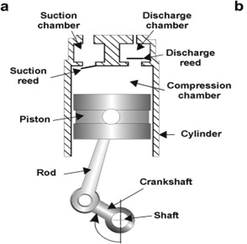
Reciprocating or Piston Compressors
This is the most widely used of all types of compressors. It uses a piston that moves up and down inside a hollow cylinder to compress the refrigerant (much like a typical car engine works).
Scroll Compressor
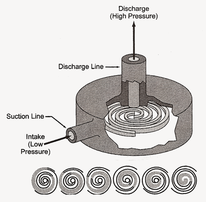
Scroll – This type compresses the refrigerant using orbiting and fixed scrolls, which squeeze the gas into 6 chambers, which decrease in volume as the scroll rotates.
Screw compressors
Screw compressors : use a pair of helical rotors or screws which mesh together to compress the refrigerant between them. They can produce high pressure for a small quantity of gas and consume less power than reciprocating compressors. They have low to medium initial and maintenance costs and few moving parts. However, they have difficulty in dirty environments, high rotational speeds, and shorter life expectancies than other designs
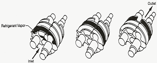
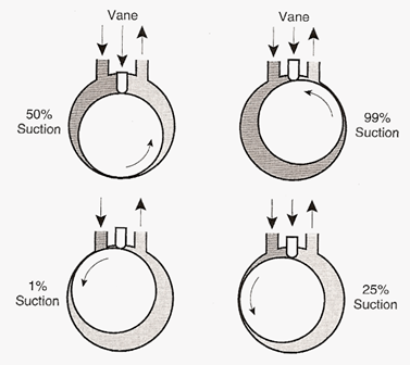
Rotary Compressors
Rotary compressors have two rotating elements, like gears, between which the refrigerant is compressed. These compressors are very efficient because the actions of taking in refrigerant and compressing refrigerant occur simultaneously. They have very few moving parts, low rotational speeds, low initial and maintenance costs, and are forgiving in dirty environments. However, they are limited to smaller volumes of the gas and produce less pressure than other types of compressors.
Centrifugal compressor
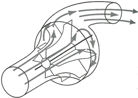
Centrifugal – The centrifugal compressor increases the refrigerant pressure by throwing it at high velocity (like an ordinary house fan throws air) using a rotating impeller inside a stationary housing. n
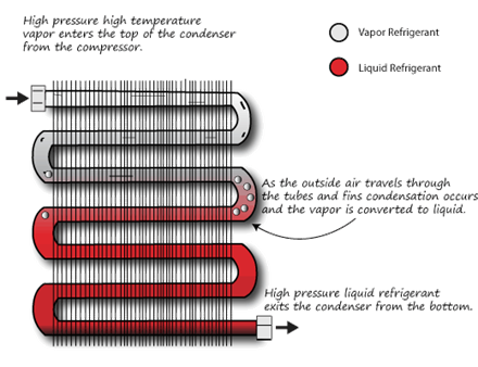
Condenser
1.Air cooled condenser
2.Water cooled condenser
Air cooled condensers (coil condensers ) are used in small units like household refrigerators, deep freezers, water coolers, window air-conditioners, split air-conditioners, small packaged air-conditioners etc. These are used in plants where the cooling load is small and the total quantity of the refrigerant in the refrigeration cycle is small. Air cooled condensers occupy a comparatively larger space than water cooled condensers.
Air cooled condensers are of two types: 1.natural convection 2.forced convection
In the natural convection type, the air flows over it in natural a way depending upon the temperature of the condenser coil. In the forced air type, a fan operated by a motor blows air over the condenser coil
Water cooled condenser :
Water is used as the heat transfer medium in place of air. Water flows through a heat exchanger where refrigerants contained in separate piping give up their heat to the water.
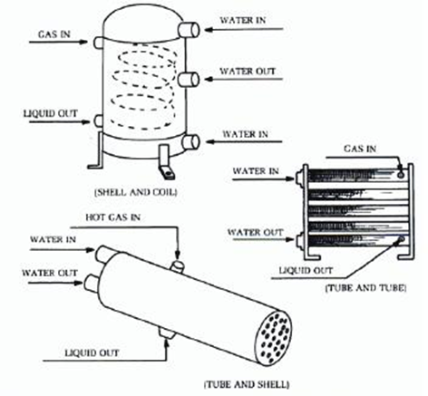
Three different Water cooled condenser
Evaporator
An evaporator is used in an air-conditioning
system to allow a compressed cooling chemical to evaporate from liquid to gas
while absorbing heat in the process. It can also be used to remove water or
other liquids from mixtures.
There are two types of evap.:
Forced Convection Type uses a fan or pump to force the liquid being cooled over the evap.
Natural Convection Type has the liquid being cooled flows naturally to the evap. due to the density differences of the chilled and warm liquid.
There are three types of evap.
1.Bare-Tube
2.Plate Surface
3.Finned construction are bare-tube coils upon which fins(metal plates usually Aluminium) are being installed.
Expansion valves
Expansion valves are devices used to control the refrigerant flow in a refrigeration system. They help to facilitate the change of higher pressure of liquid refrigerant in the condensing unit to lower pressure gas refrigerant in the evaporator.
Types.
1. Automatic Exp. Valves
regulates the flow of refrigerant from the liquid line to the evaporator by using a pressure-actuated diaphragm. It maintains a constant pressure in the evaporator.
2. Thermostatic Exp. Valves : uses a valve mechanism to control the flow of liquid refrigerant into the evaporator coil. The flow is controlled by the pressure in the evaporator.
3.Capillary Tubes is a tube with small internal diameter and could be coiled for part of its length. It is installed to the suction line. A filter-drier is sometimes fitted before the tube to remove dirt or moisture from the refrigerant.
4. Float Valves is actuated by a float that is immersed in the liquid refrigerant. Both low-side float and high side-float are used to control the flow of liquid refrigerant
Refrigerant in Refrigeration
Chemical Refrigerant A refrigerant is a compound used in a heat cycle that undergoes a phase change from a gas to a liquid and back. The two main uses of refrigerants are refrigerators/freezers and air conditioners.
Refrigerant Properties: Special Thermodynamic qualities such as suitable
- boiling point (somewhat below the target temperature),
- high heat of vaporization, moderate density in liquid form,
- high density in gaseous form,
- Non-corrosive,
- Non-toxic and safe.
Refrigerant Examples: – •Ammonia (boiling point: -33ºC) •Freon 12 (R-12) (boiling point: -30ºC) •Freon 22 (R-22) (boiling point: -40ºC) •Dry ice (CO2) (boiling point: -73ºC) •CFC (chlorofluorocarbon) •HCFC(hydrochlorofluorocarbon) •HFC (hydrofluorocarbon)
Currently most widely used Refrigerants:
R-134a (CH2FCF3, boiling point: -26ºC)
R-410a (50% CH2F2/50%CHFCF3, boiling point: -48ºC)
Unit of refrigeration
A ton of refrigeration (TR), also called a refrigeration ton (RT), is a unit of power used to describe the heat-extraction capacity of refrigeration and air conditioning equipment. It is defined as the rate of heat transfer that results in the melting of 1 short ton of pure ice at 0 °C (32 °F) in 24 hours.
Unit of refrigeration Domestic and commercial refrigerators may be rated in kJ/s, or Btu/h of cooling. Prior to the introduction of mechanical refrigeration, cooling was accomplished by delivering ice. Installing one ton of mechanical refrigeration capacity replaced the daily delivery of one ton of ice.
Latent heat of ice (i.e., heat of fusion) = 333.55 kJ/kg = 144 Btu/lb
One short ton = 2000 lb = 907 kg
Heat extracted = 2000 x 144/24 hr = 288000 Btu/24 hr = 12000 Btu/hr = 200 Btu/min
1 ton = 200 Btu/min = 3.517 kJ/s = 3.517 kW = 4.713 HP
Air cooling and air conditioning
The main difference between air coolers and air conditioners is the first runs air through water, reducing the temperature through evaporative cooling while the other uses refrigerants to absorb heat, push out cold air and reduce humidity to cool the room.
Design consideration
As per clause 4.2.1 of NBC 2016 part 8 section 3 following factors shall take into account in planning of HVAC system :
- Recommended indoor temperature, relative humidity, air velocity, mean radiant temperature, clothing and activity
- Outside design conditions
- Details of building construction and orientation of exposures of building components;
- Fenestration area and shading factors
- Occupancy – Number of people and their activity
- Ventilation – Requirement for fresh air
- Infiltration, air leakage
- Internal Load – Lighting and other heat generating sources like computers, equipment and machinery
- Effective volume
- Occupancy, lighting and equipment schedule
Thermal comfort
Criteria for Thermal Comfort :
Thermal comfort is that condition of surrounding thermal environment under which a person can maintain a body heat balance at normal body temperature without perceptible sweating. Thermal comfort is highly subjective and limits of comfort vary from person to person. Human thermal comfort is dependent on following factors :
The four environmental factors are:
- Dry bulb temperature
- Mean radiant temperature
- Relative Humidity
- Air Velocity
In addition to environmental factors there are two physiological factors that affect a person’s thermal comfort, which are
- Metabolic rate
- Clothing level
Psychrometric Chart
History :
The Psychrometric chart – 1904
Willis H. Carrier’s historic paper “Rational Psychrometric formulae”, 1911
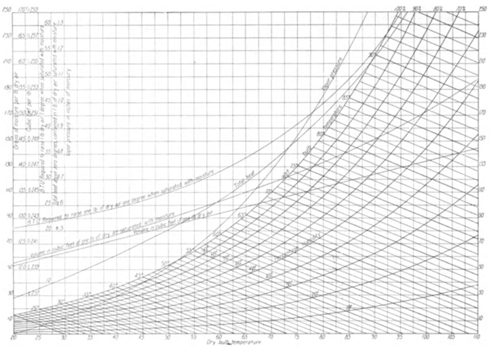
A Psychrometric chart is a graphical representation of physical and thermodynamic properties of environment such as Dry bulb temperature, Wet bulb temperature, Relative Humidity, enthalpy, and air density.
Psychrometric Chart – Dry-bulb temperature (DBT)
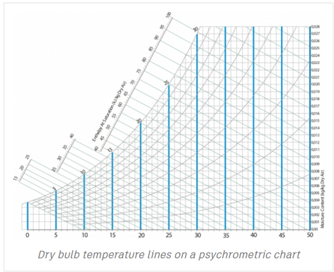
The dry-bulb temperature (DBT) is the temperature of air measured by a thermometer freely exposed to the air but shielded from radiation and moisture.
DBT is the temperature that is usually thought of as air temperature, and it is the true thermodynamic temperature. It indicates the amount of heat in the air and is directly proportional to the mean kinetic energy of the air molecules.
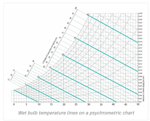
Psychrometric Chart – Wet-bulb temperature (WBT)
The Wet Bulb temperature is the adiabatic saturation temperature.
Wet Bulb temperature can be measured by using a thermometer with the bulb wrapped in wet muslin. The adiabatic evaporation of water from the thermometer bulb and the cooling effect is indicated by a “wet bulb temperature” lower than the “dry bulb temperature” in the air.
The rate of evaporation from the wet bandage on the bulb, and the temperature difference between the dry bulb and wet bulb, depends on the humidity of the air.
Psychrometric Chart -Relative Humidity
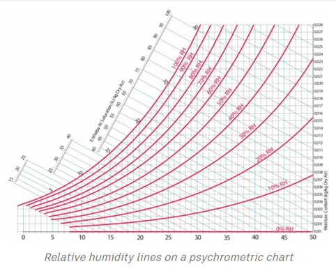
Relative Humidity is the amount of water vapour present in air expressed as a percentage of the amount needed for saturation at the same temperature.
When the air is saturated, dry-bulb, wet-bulb and dew point temperatures are all equal, and the relative humidity is 100 %
Psychrometric Chart -Dew point (DP) temperature
This is the temperature of the air at which a moist air sample reaches water vapor saturation. It is equivalent to a wet bulb temperature at 100% relative humidity. At this combination of temperature and humidity, further removal of heat results in water vapor condensing into liquid.
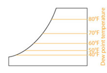
A practical view of the dew point is the temperature to which air must be cooled before condensation will begin. An example is when you take a bottle out of the refrigerator. Water condenses on the outside of the bottle only if the original temperature of the bottle was below the dew point. The instantaneous temperature of the water is the dew point temperature.
Psychrometric Chart -Moisture content
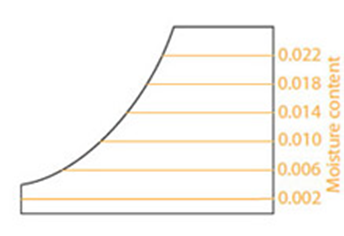
This is also known as the humidity ratio. It is the proportion of the mass of water vapor per unit mass of dry air.
Humidity ratio is dimensionless, it may
be expressed as grams of water per kilogram of dry air or as a
percentage.
The moisture content is the vertical axis of the chart.
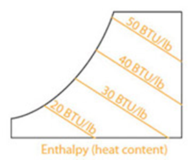
Psychrometric Chart – Enthalpy (total heat)
nEnthalpy (h) is the total amount of heat energy of the moist air and therefore includes the amount of heat of the dry air and the water vapor in the air. nIn the approximation of ideal gases, lines of constant enthalpy are parallel to lines of constant WB temperature. Thus the enthalpy is indicated by diagonal lines on the chart.
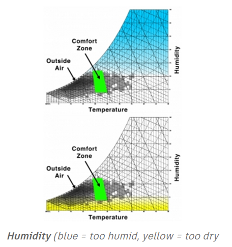
Interpreting the Psychrometric Chart
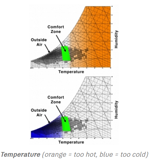
Importance of Psychrometric chart in the HVAC industry : npeople feel comfortable over a narrow range of temperature and humidity nmachines (especially electronic machines) operate over a specific range of temperature and humidity nto calculate the amount of heating or cooling required for a certain space requires knowledge of the moisture content of the air n
Psychrometric charts provide a rapid overview of air conditions as they relate to occupant comfort, some steadfast judgments can be made. For example, is your climate hot and humid, or dry and arid? How are your occupants going to feel most of the time—too hot, too cold, or comfortable?
Application of Psychrometric chart
Effect of Temperature on Humidity
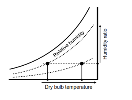
•The moisture-holding capacity of the air depends on the air temperature. •Warm air can hold more moisture than cold air. •The same humidity ratio results in different relative humidities at different temperatures.
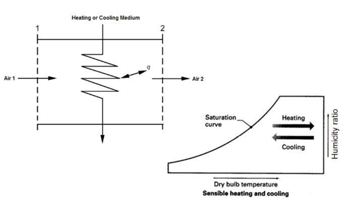
Sensible Heating and Cooling
Horizontal movement on the psychrometric chart (no change in absolute humidity)
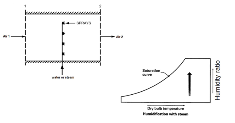
Humidification
Humidification with steam or water spray will increase the humidity ratio and relative humidity.
Dehumidification
Cooling is the most common method for dehumidifying moist air.
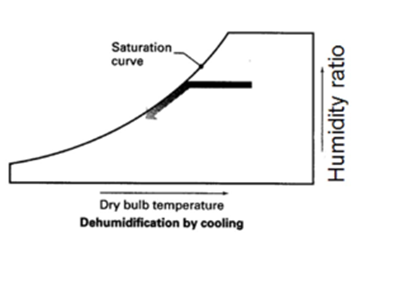
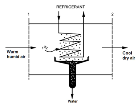
If moist air is cooled to the saturation curve, further cooling will reduce temperature and remove moisture
Evaporative Cooling
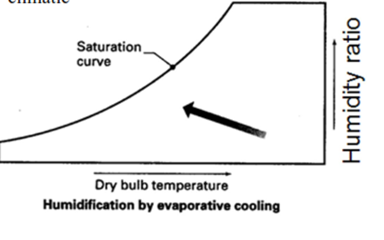
•Evaporative cooling can be accompanied by humidification of warm dry air.
•Sensible heat loss = Latent heat gain (no change in enthalpy)
•Upward movement along a line of constant enthalpy
•Energy saving cooling device in hot-dry climatic regions.
Application of Psychrometric chart in Architecture
Psychrometric Chart could be found in the special software(Climate Consultant) which could be taken from website for free.
To access the data we need input weather files, which are distributed for free on the same website (most of the cities in the world could be found there, however i was trying to find the place where i live and it is not available).
Once we open a weather file the most interesting part begins! The software shows you the range of comfort conditions with the quadrangle.
The legend shows the design strategies we can use, it provides information of how reasonable is the particular strategy and how many hours would be effective.
Each strategy is marked with particular color and we can actually see how the strategy extends the comfort zone.
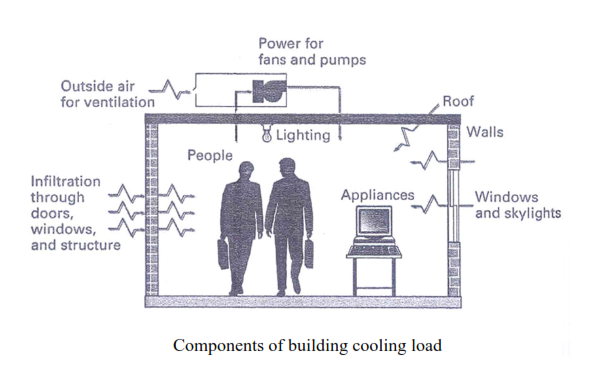
Cooling load
The cooling load is equivalent to the rate at which heat must be extracted in order to maintain a constant indoor temperature
The component of cooling load
1.Heat gain during summer due to conduction, convection, or radiation are all sensible load which tend to increase the DBT of room air
2.The Transmission load is positive gain in summer
3.People loss part of their body heat by perspiration which is a latent load which tends to increase the moisture content of the air
4.The ventilation air drawn in from outside can be both a sensible and latent load.
Space load ( SL) is maximum sensible heat generated in the space
SL = Solar radiation + Transmission+ Electric power+ People (sensible heat)
Equipment Load ( EL) is maximum total heat transferred to the cooling coil ( including that for cooling / dehumidifying the ventilation air )
EL = Solar radiation + Transmission+ Electric power + People + Outside Air
Cooling load calculation using CLTD/CLF Method
CLTD/CLF Method (classical)
- Cooling load is made up of
- Radiation and conduction heat gain
- Convection heat gain
- Convective gain is instantaneous
- No delay
- Heat gain equals cooling load
- Conductive and radiation heat gains are not instantaneous
- Thermal delay
- Heat gain is not equal to cooling load
- Use CLTD & CLF factors
CLTD/CLF Method (ASHRAE 1989)
Cooling load due to solar & internal heat gains
- Glazing (sensible only)
- Radiation & conduction
- Convection (instantaneous)
- Opaque surface ( wall, floor, roof) load (sensible only)
- Conduction
- Convection (instantaneous)
- Internal loads (sensible & latent)
- Radiation & conduction
- Convection (instantaneous)
CLTD/CLF Method
Cooling Load Temperature Difference CLTD
Compare
Q transmission = UA (To – Ti)
Q transmission = UA (CLTD)
• CLTD is theoretical temperature difference defined for each wall/roof to give the same heat load for exposed surfaces to account for the combined effects of radiation, conductive storage, etc
– It is affected by orientation, time , latitude, etc
– Data published by ASHRAE
Cooling Load Factor (CLF)
• This factor applies to radiation heat gain
• If radiation is constant, cooling load = radiative gain
• If radiation heat is periodical, than
Q t = Q daily max (CLF)
CLF accounts for the delay before radiative gains becomes a cooling load
Cooling load due to solar heat gains Glazing
Q = A (SC) (SHGF) (CLF)
A= glass area
SC= shading coefficient
SHGF= solar heat gain factor, tabulated by ASHRAE
CLF= cooling load factor, tabulated by ASHRAE
Q = U x A x CLTD
U= surface U-factor
A= surface area
CLTD= cooling load temperature difference
SC(shading coefficient)
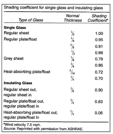
The SC is the ratio of solar gain (due to direct sunlight) passing through a glass unit to the solar energy which passes through 3mm Clear Float Glass.
It is referred to as an indicator to how the glass is thermally insulating (shading) the interior when there is direct sunlight on the panel or window.
Types of Internal Load
Types of Internal Load are
- Internal loads are
- People
- Lights
- Equipment or appliances
- Consist of convective and radiant components
- Light (mostly radiant)
- Electrical heat (radiant and convective)
- People (most convective)
- Time-delay effect due to thermal storage
Internal Load- Lighting
•Heat gain (lighting)= 1.2 x total wattage x CLF
Or based on light power density ranging from 10-25 W/m2(average density, say=20 W/m2) •Where light is continuously on, CLF=1
| Area | Light Power Density W/m2 |
| Office | 25 |
| Corridor | 10 |
| Sleeping | 10 |
| Recreation | 20 |
| Bus terminals | 25 |
| Kitchen | 25 |
Total heat gain from the occupants
Table shows typical values of total heat gain from the occupants and also the sensible heat gain fraction as a function of activity in an air conditioned space.
Activity Total heat gain, W Sensible heat gain fraction
Sleeping 70 0.75
Seated, quiet 100 0.60
Standing 150 0.50
Walking @ 3.5 kmph 305 0.35
Office work 150 0.55
Teaching 175 0.50
Industrial work 300 to 600 0.35
Q people-s= No x sensible heat gain/p x CLF
Q people-L= No x latent heat gain/p
Cooling load for various Building based on rules-of-thumb
(Croome and Roberts, 1981)
Sl.no Application Required cooling load (TR) for 1000 ft2 of floor area
1. Office buildings:
- External zones 25% glass: 3.5 TR
- 50% glass: 4.5 TR
- 75% glass: 5.0 TR
- Internal zones 2.8 TR
2. Computer rooms 6.0 – 12.0 TR
3. Hotels
- Bedrooms
- Single room: 0.6 TR per room
- Double room: 1.0 TR per room
- Restaurants 5.0 – 9.0 TR
4. Department stores
- Basement & ground floors 4.5 – 5.0 TR
- Upper floors 3.5 – 4.5 TR
5. Shops 5.0 TR
6. Banks 4.5 – 5.5 TR
7. Theatres & Auditoriums 0.07 TR per seat
The average cooling load in W(R) / m2 of air conditioned floor area are shown below for thirty different configuration of multi-storey office . The values have been computed for
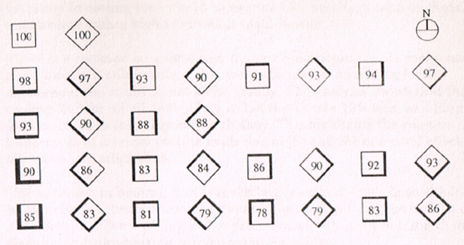
- 1000m2 square floor
- 50% glazing
- Solar shading factor of 0.425
- Population density = 10m2 /person
- Electric load = 32 W / m2
- Outside air = 5 L / s. per person
Indian Standards (IS CODE) for HVAC
| IS CODE | Title |
| IS 659 : 1964 | Safety codes for air conditioning (revised) |
| IS/ISO 817 | Refrigerants . Designation and safety classification (second revision) (Under print) |
| IS 1391 | Specification for room air conditioners: |
| (Part 1) : 1992 | Unitary air conditioners (second revision) |
| (Part 2) : 1992 | Split air conditioners (second revision) |
| IS 2379 : 1990 | Colour code for identification of pipelines (first revision) |
| IS 3315 : 1994 | Specification for evaporative air coolers (desert coolers) (second revision) |
| IS 8148 : 2003 | Specification for packaged air conditioners (first revision |
Forum Threads
Download PDF for Educational Purposes Only
Register in Front Desk Architects & Planners Forum to download above PDF
Disclaimer
Information on this site is purely for education purpose. The materials used and displayed on the Sites, including text, photographs, graphics, illustrations and artwork, video, music and sound, and names, logos, IS Codes, are copyrighted items of respective owners. Front Desk is not responsible and liable for information shared above.