- FORUM
- PROJECTS
- ABOUT US
- RESOURCES
- CONTACT US
- FORUM
- PROJECTS
- ABOUT US
- RESOURCES
- CONTACT US
Sound Insulation
Sound is transmitted through most walls and floors by setting the entire structure into vibration. This vibration generates new sound waves of reduced intensity on the other side. The passage of sound into one room of a building from a source located in another room or outside the building is termed ”sound transmission”.
Transmission loss or Sound Reduction Index, R dB, is a measure of the effectiveness of a wall, floor, door or other barrier in restricting the passage of sound. The transmission loss varies with frequency and the loss is usually greater at higher frequencies. The unit of measure of sound transmission loss is the decibel (dB). The higher the transmission loss of a wall, the better it functions as a barrier to the passage of unwanted noise.
There are two types of sound insulation in buildings: airborne and impact. Airborne sound insulation is used when sound produced directly into the air is insulated and it is determined by using the sound reduction index. Impact sound insulation is used for floating floors and it is determined by the sound pressure level in the adjacent room below.
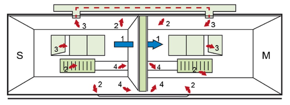
- Direct sound transmission
- Flanking transmission
- Overhearing
- Leakage
a) Airborne sound insulation
When a sound wave is incidental upon a partition between two spaces, part of it is reflected and part of it is transmitted through the partition.
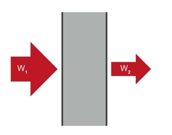
R = 10log10 W1/W2
| R (dB) | W1/W2 |
| 0 | 1 |
| 10 | 10 |
| 20 | 100 |
| 30 | 1 000 |
| 40 | 10 000 |
| 50 | 100 000 |
| 60 | 1 000 000 |
For single leaf structures, such as a homogenous concrete wall, the transmission follows the mass law, that is, the more massive the structure, the smaller the quantity of transmitted sound.
In case of lightweight structures consisting of multiple layers, such as a gypsum wall, the spring-mass law is applicable. If highly absorbent material such as stone wool is used as the spring in a double leaf wall, the sound insulation improves. The wider the cavity, the greater the benefit from stone wool will be. Typically, a 5 – 10 dB increase in R can be achieved with a filled cavity compared to an empty one. The figure below shows a single leaf structure and a double leaf structure with the same total weight.
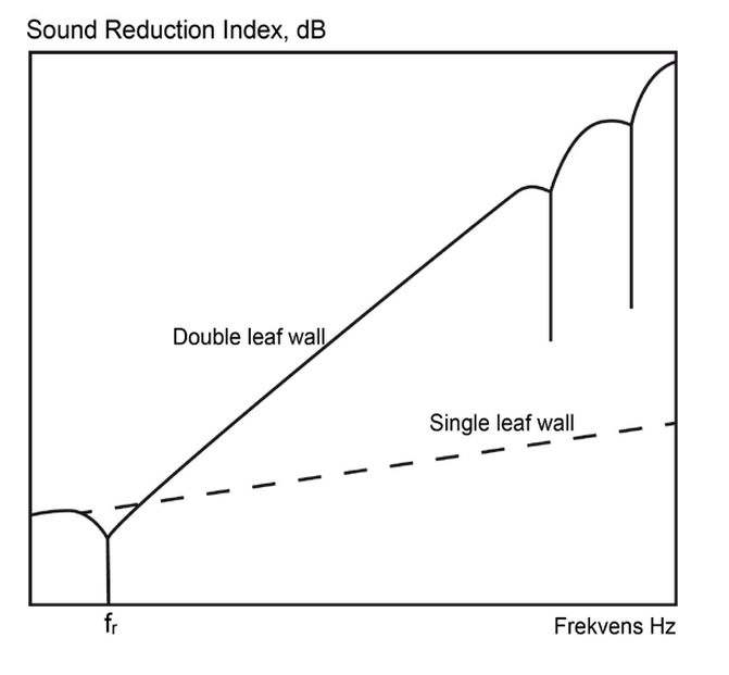
Calculation of the sound reduction index R is based on test results obtained at different frequencies. The results are plotted against the reference curve between 100 Hz and 3150 Hz at 1/3-octave intervals. If the measurements are performed in situ (in a real building) the values are denoted R’. The standard test procedure is defined in EN ISO 140, where standard methods are given for both laboratory and field measurements.
The difference between laboratory and field values can be a significant number of dB depending on the const ruction details and workmanship.
If a partition consists of different kinds of elements – for example, a wall with windows and doors which have different sound transmission characteristics – the overall sound reduction index must be calculated.
The sound reduction index for holes and slits is nearly equal to 0 dB. The influence of holes and slits may therefore be important, for instance, at the connections between walls, at doors and windows without sealing strips, and at any necessary openings in partitions. If there is an acoustically absorbing material in the slits, it will give a higher sound reduction index for the slits.
Weighted Sound Reduction Index Rw
When specifying the acoustic performance of a partition in a more general manner, it can be useful to describe the sound insulation by a single number. The weighted sound reduction index, Rw , is a rating method given in EN ISO 717-1. This standard fits a standard reference curve to the measured sound reduction index curve
In EN ISO 717-1, a rating method is also given where the Rw value is completed by two C-terms which are applied to two models of the noise spectra for various types of noise. These two terms, Rw + C and Rw + Ctr, also include the frequency range 100 – 3150 Hz but can be extended to 50 – 5000 Hz. As industrial and traffic noise often have high sound levels which are also below 100 Hz, it is recommended that the extended frequency area is used.
The summary value, Rw + C, gives the reduction value in dBA for a spectrum with a level which is equally high in all third-octave bands. This can be used for:ul>Living activities (talking, music, radio, TV)Railway traffic at medium and high speedHighway road traffic travelling at speeds in excess of 80 km/hJet aircraft at a short distanceFactories emitting mainly medium and high frequency noise
The summary value Rw + Ctr also gives the reduction value in dBA, spectrum with low-frequency dominance such as:
- Urban road traffic
- Railway traffic at low speeds
- Disco music
- Factories emitting mainly low and medium frequency noise
b) Impact sound insulation
An airborne source sets up vibrations in the surrounding air which spread out and, in turn, set up vibrations in the enclosing walls and floors. An impact source sets up vibrations directly in the element it strikes. These vibrations spread out over the whole area of the element and into elements connected to it, such as internal walls, the inner leaves of external walls and floors. The vibrations in the elements force the air beside them to vibrate and it is these new airborne vibrations that are heard.
Floors should reduce airborne sound and also, if they are above a dwelling, impact sound. A heavy solid floor depends on its mass to reduce airborne sound and on the soft covering to reduce impact sound at source.
A floating floor contains a layer of highly resilient material which largely isolates the walking surface from the base and this isolation contributes to both airborne and impact insulation.
- It is important to choose a suitable material and to make sure that is not bypassed with rigid bridges such as fixings and pipes.
- Air paths, including those due to shrinkage, must be avoided; porous materials and gaps at joints in the structure must be sealed.
- Resonances must also be avoided; these may occur if some part of the structure (such as dry lining) vibrates strongly at a particular sound frequency (pitch) and transmits more energy at this pitch.
Impact sound insulation is calculated from measurements of the sound pressure level produced by the standardised hammer method. The results are presented as a curve between 50 – 5000 Hz.
When calculating a single-number quantity L n,W or L’n,W the levels for the 16 frequencies are compared to the standard curve in a similar manner to the calculation of the sound reduction index. The only difference is that the deviation between the measured curve and the standard curve is in this case above the standard curve. Ln is measured in the lab whilst L’n is measured in the field. For both Ln and L’n low numerical values mean good impact sound insulation.
Also for impact sound insulation, two spectrum adoption terms Ci,100-2500 and Ci,50-2500 are needed in case of a floor with wooden beams. The difference between the results of laboratory and field measurement is caused by the flanking phenomena in a building. In a real building, sound transfers not only through a structure being designed – for example, a floor – but also via connecting structures adjacent to the floor.
Dynamic stiffness
Dynamic stiffness is a very important property for porous materials, especially when the material is mounted directly between two solid layers (sandwich-element, floating floor). For mineral wools, it is presented per unit MN/m3 because mineral wool is usually continuous.
Stone wool is composed of solid material and air. When it is used as a resilient layer, we have to determine dynamic stiffness for both mineral fibres and air separately; so dynamic stiffness = sd + sa (sd is the material stiffness and sa is the stiffness for enclosed air).
In accordance with testing standards, the dynamic stiffness of stone wool must be stated for a loading of 200kg/m2 when it is used under a floating concrete floor. The lower the dynamic stiffness values, the better the impact sound insulation.
The stone wool products used as step sound insulation are specially designed for floor application. The fibre orientation is mainly horizontal compared to, for example, roof slabs or ground slabs. The horizontal fibres block better the sound from passing through. The difference when used in a floor may be 5 dB or even more. This means a one class difference.
Mass-spring system
The main idea behind the floating floor is the mass-spring system. The softer the spring, the better the vibration damping. The same goes with the mass – the heavier the better. If the intermediate floor is not heavy, the floating floor does not work because the mass-spring system changes. In practice, an intermediate floor has to be five times heavier than a floating floor.
Impact noise insulation is measured using a standardised tapping machine. A good impact noise insulation L’n,w requires:
Concrete with a floating floor:
- Heavy intermediate floor
- Soft elastic intermediate layer
- Heavy floating floor
The ideal mass-spring system:
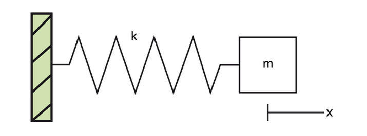
At the extremes of its displacement, the mass is at rest and has no kinetic energy. At the same time, the spring is maximally compressed, and thus stores all the mechanical energy of the system as potential energy. When the mass is in motion and reaches the equilibrium position of the spring, the mechanical energy of the system has been completely converted into kinetic energy.
All vibrating systems consist of this interplay between an energy-storing component and an energy-carrying component.
The frequency (Hz, the number of vibrations per unit time) of a mass-spring system is
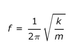
Where k is the spring constant (mineral wool) and m is the mass (intermediate floor). The lower the f is, the better the insulation. So by increasing the mass or decreasing the spring constant we can achieve the best insulation.
c) Flanking transmission
Flanking transmission is a more complex form of noise transmission where the resultant vibrations from a noise source are transmitted to other rooms of the building usually by elements of structure within the building. For example, in a steel framed building, once the frame itself is set into motion the effective transmission can be pronounced.
In a building, a fraction of the sound transmission between two rooms may go by a flanking building element, such as the outer wall or the ceiling. In order to avoid this, the manufacturer’s instructions must be followed carefully. The figure shows the principal solutions for an outer wall.
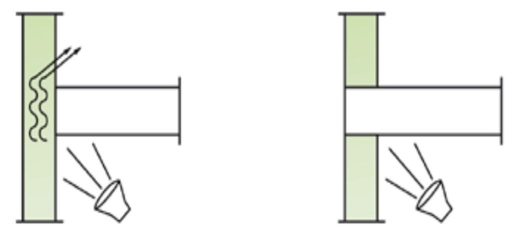
Solutions for reducing the risk of flanking transmission
There are often requirements for a safety margin in the different sound data of the elements in order to avoid flanking transmission.