Creating a complete electrical drawing for a building involves various elements, such as lighting, power outlets, switches, and distribution panels. Electric symbols of various elements use in the drawing is as per IS code 2032 Part-11-1969
Type of Electrical drawings
- Electric layout plan
- Electric wiring plan
- Electric switch socket layout
- Distribution box Single Line Diagram (SLD)
- Single Line Diagram (SLD) with load computations
Electrical – Basis of design
First consultant have to finalize the Electrical – Basis of design with client for example :
- All the rooms, bedrooms/drawing / dining will have false ceiling and thus recess lights as per the interiors. It is suggested that at this stage we make arrangements for three lighting circuits, of 500 W each, to be left in the ceiling in all the bedrooms and three lighting circuits, of 800 watts each, to be left in the ceiling of the drawing, dining, lounge/ lobby.
- Provision for Generator and inverter system. To have a light in each room on inverter power supply and the balance on generator, in case of power failure.
- All the mirrors in toilets to be provided with a electrical point behind them – for Anti fog Mirror to be installed.
Electric layout plan
Electric layout plan shows the position of electrical switches, sockets, I.T. voice and data points, 2 way switch points, 16mp points for heavy electrical equipments, wifi points in ceiling, A.C. placement etc over the interior and exterior walls. These drawings are important for planning a space and how it will be used
Electric wiring plan
Electric wiring diagrams are given in this section which will be useful during electrification work in a building. Following points must remember while doing wiring –
- PVC conduit is used for house wiring,
- The size of conduit depends on the number & size of wires,
- Two types of conduiting are done -1) Surface & 2) Concealed,
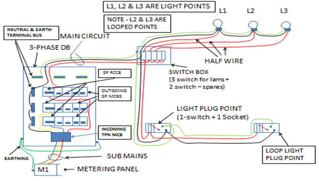
- Sub-Mains– Submain is a set of wires which is laid between the DB (Distribution Board) of the house & metering panel. The size of submains should be capable to carry current of total load which is connected with DB. Sub-mains are of two types –
- Three phase submains (3-phase wires R,Y,B + 1-neutral wire + 1- earth wire)
- Single phase submains (1-phase wire + 1-neutral wire +1- earth wire).
- Main Circuit– It is a set of 3 wires (1-phase, 1-neutral & 1-earth) which is laid inside the conduit between DB & first switch box. First switch box may be for lighting purpose or for switch& socket. Main circuit for light & light plug is fed from 10A MCB. Maximum 800W load can be connected with one main circuit or maximum 10 nos of points can be connected with one circuit. While main circuit for power point (16A switch & socket) is fed from 16A MCB.
- Half wire (First light point) – It’s a phase wire which is laid between switch & light point. This light point is called first light point.
- Loop point (Secondary light point)– Loop point is secondary point which is connected/looped with first point. Next loop point may be connected with first loop point & so on.
- point– It’s either a light or power point where light or equipment are connected. Light is connected with light point & equipment is connected with power points.
- Light plug – Light plug is a set of 6A switch & socket which is used for low current portable equipment like TV, RO, portable fan, mobile charger etc. Light plug is fed with 10A MCB or may be looped with light point.
- Power plug – Its set of 16A switch & socket which is used for high current portable equipments like domestic iron, geyser, refrigerator, AC, Heater etc. Power plug is fed from 16A/20A/25A depending upon the type of load.
Wire current capacity
One can use thumb rule for calculate wire current capacity by multiplying the size of the wire in square millimeters by 6. For example, for 2.5 square millimeters, the calculation is 6 x 2.5 = 15 amps
| Size of Cu wire (in sq mm) | Size of Al wire (in sq mm) | 50% Safe Current (in Ampere) | 50% Safe wattage in 230 Volt line(KW) | Used in |
| 0.75 | 5 | 0.5 | ||
| 1 | 1.5 | 6 | 0.69 | |
| 1.5 | 2.5 | 7.5 | 1.0 | Fan & light |
| 2 | 3 | 10 | 1.3 | |
| 2.5 | 4 | 15 | 2.4 | AC IDU & UPS circuit , Light Circuit |
| 4 | 6 | 27.5 | 5.0 | Power circuit |
| 6 | 9 | 37.5 | 6.9 | |
| 10 | 15 | 50 | 9.2 |
Notes :
- A circuit shall not have more than 10 points of light, fans & 6A socket outlets. And the load of such circuit shall be restricted to 800W & wiring with 1.5 mm2 copper conductor.
- If a dedicated circuit is planned for light fixtures, the load of such circuit shall be restricted to 400W with wiring 1.5 mm2 copper conductor.
- If a dedicated circuit is planned for 6A sockets, the load of such circuit shall be restricted to 800W or a maximum of 8 numbers socket.
Typical 3 bed house wiring
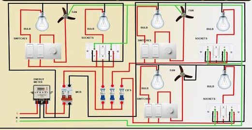
Typical 3 light point wiring
Electric switch socket layout
Switch – Switch is a device that is used to switch on or switch off power supply of lights, power points etc. Various types of switches are used for domestic & office purpose.
Socket – Sockets are used to connect electrical load such as heater, refrigerator, induction plate, TV, washing machine, AC, iron, table (portable) equipment such as table lamp etc.
A switch and socket layout drawing shows the number of electrical switches, sockets fitted in a specific switch box (SB) or light point (LP) module. following information are mentioned is each SB and LP
- Height of Switch Box.
- Number of modules provided in Switch Box.
- Thickness of circuit wire in MM connecting with DB
- Number of 16 Amp Switch.
- Number of 6 Amp Switch or 2 way Switch
- Number of 16 Amp Socket
- Number of 6 Amp Socket
- Fan Regulator
- Number of Blank
- Number of 25 Amp Switch.
These drawings are important for electric wiring and switch box module planning a space and how it will be used , sample drawing can be download from following link..
ELECTRICAL SWITCH SOCKET LAYOUT.pdf
| SIZE OF BOX (In Inches) | NUMBER OF MODULES PROVIDED |
| 3”x3” | 2 Module |
| 3”x4” | 3 Module |
| 3”x6” | 4 Module |
| 3”x8” | 6 Module |
| 6”x6” | 8 Module |
| 6”x8” | 12 Module |
| 12″x12″ | 16 Module |
Sockets are available in – 6A, 16A, capacity.
6A socket is used for low watts load such as mobile charger, computer charger, laptop charger, table lamp, TV etc. It’s a 3pit socket. Two small dia bottom pins are used for phase & neutral & top big pin is used for earthing purpose.
16A socket is used for high watts load such as refrigerator, geyser, iron, AC etc.
6/16ASocket is used for both low & high watts load. It is a 5 pin socket. Top big round pin for earthing, next lower two round pins for low watts load while last two bottom pins for high watts load.
MAXIMUM PERMISSIBLE NUMBER OF SINGLE CORE CABLES UP TO & INCLUDING 1100V THAT CAN BE DRAWN INTO RIGID STEEL CONDUITS (as per NBC-2016)
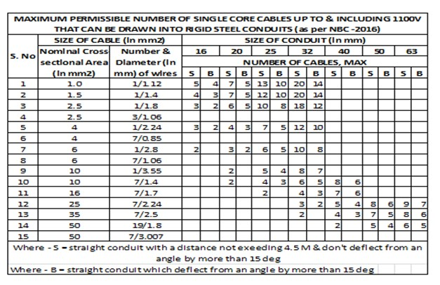
Cable Trunking/Cable Ways
Cable trunking and ducting system of insulating material are used for surface wiring. The number of insulated conductors that can be drawn into cable trunking and ducting system are given in Table
| Maximum Permissible Number of PVC Insulated 650/1100 Grade Aluminum/Copper Cable Confirming to Accepted Standard (8-2(3)) that can be drawn into Cable Trunking /Cable Ways | |||||||
| S. No | Nominal Cross-Sectional Area of Conductor mm2 | 10/15 mm x 10mm | 20/15 mm x 10mm | 25/15 mm x 16mm | 32mm x 16mm | 40mm x 25mm | 40mm x 40mm |
| i | 1.5 | 3 | 5 | 6 | 8 | 12 | 18 |
| ii | 2.5 | 2 | 4 | 5 | 6 | 9 | 15 |
| iii | 4 | 2 | 3 | 4 | 5 | 8 | 12 |
| iv | 6 | 2 | 3 | 4 | 6 | 9 | |
| v | 10 | 1 | 2 | 3 | 5 | 8 | |
| vi | 16 | 1 | 2 | 4 | 6 | ||
| vii | 25 | 1 | 3 | 5 | |||
| viii | 32 | 2 | 4 | ||||
| ix | 50 | 1 | 3 | ||||
| x | 70 | 1 | 2 | ||||
Distribution box Single Line Diagram (SLD)
Distribution box Single Line Diagram (SLD).pdf
Wiring norms from NBC 2016
- It is preferable to have additional circuit for kitchen& toilet,
- If a separate fan circuit is provided, the number of fans in the circuit shall not exceed 10.
- Power sockets shall be designed according to load. But in no case, there shall not be more than two 16A outlets on each sub circuits with wire 4 mm2 copper conductor with load limit to 1Kw each.
- It is a practice to limit two sockets in a circuit , in both residential & non-residential buildings & to provide single socket on a circuit for a known heavy load appliances such as AC & cooking range etc.
- DB shall be fixed on suitable sanctioned wall and shall not be more than 1.8m from floor level.
- In India, nominal values of low & medium voltage systems are 240V & 415V ac respectively & the frequency is 50Hz.
- For conductor sizes less than or equal to 16mm2, only copper conductor cables should be used as Aluminum conductor cables in sizes less than 16mm2 cause termination problem leading to heating at terminals & enhance the possibility of a fire.
- Switch & isolator controlling a water heater or geyser should not be located within 1 m from the location of a shower or bath tub, to avoid a person in wet condition. It is preferable to provide the control switch outside the bath room near the entrance & provide an indication at water heater.
- Sockets in kitchen, bathroom toilet, garage etc should not be provided within a height of 1m from the ground level. Similar care has to be taken for installations involving foundations, swimming pools etc.
- Light fitting is such areas should be fed at low voltage, preferably though an isolating transformer with a proper earth leakage protection – 100/30mA RCCB/RCD as applicable.
Estimation of Load Requirements
In estimating the current to be carried by any wire / cable, the following ratings shall be taken, unless the actual values are known or specified for these elements. For this, refer table given below.
| S. No. | Element | Rating (W) |
| i) | Incandescent lamp | 60 |
| ii) | Ceiling Fan | 60 |
| iii) | Table fan | 60 |
| iv) | 6A Socket outlet | 100, unless the value of actual load is specified |
| v) | 16A Socket outlet | 100, unless the value of actual load is specified |
| vi) | Fluorescent Lamp:Length:a) 600 mmb) 1200 mmc) 1500 mm | 255090 |
| vii) | High Pressure Mercury Vapour (HPMV) lamps, High pressure sodium vapour (HPSV) lamps | According to their capacity, control gear losses shall be also considered as applicable |
| viii) | Compact fluorescent lamp (CFL) | 20 |
| ix) | Light emitting diode (LED) | 10 |
| x) | Exhaust fan | 50 |
| xi) | Geyser (storage type) | 2000 |
| xii) | Geyser (instant) | 3000 |
| xiii) | Computer point | 150 |
| xiv) | Computer (laptop) | 50 |
| xv) | Printer, laser | 1500 |
| xvi) | Printer, inkjet | 70 |
| xvii) | Kitchen outlet | 1500 |
| xviii) | Air conditioner: | |
| 1 TR | 1250 | |
| 1.5 TR | 1875 | |
| 2 TR | 2500 | |
| 2.5 TR | 3200 |
FD Architects Forum Discussion
- National Electric Code (NEC)
- ELECTRICAL LOAD CARRYING CAPACITY OF COPPER WIRES OF DIFFERENT THICKNESS
- ELECTRICAL SWITCH SOCKET LAYOUT
- Distribution box Single Line Diagram (SLD)
- Some common terms used in electrical services
- MAXIMUM PERMISSIBLE NUMBER OF CABLES